
Motivation
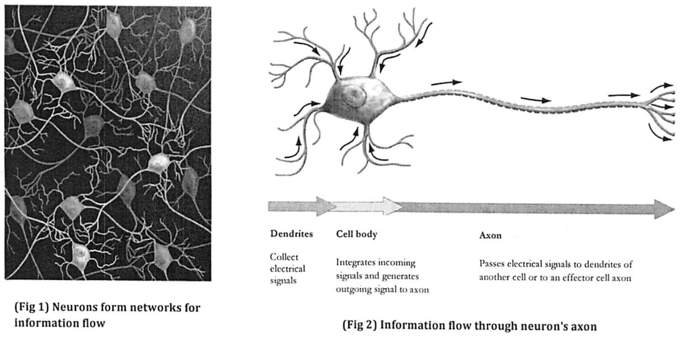
Nerve impulses travel in our bodies as electrical signals. Whether it’s seeing or hearing something, controlling a muscle, or just thinking, the transmission process along a nerve cell, or neuron, is the same: a sufficient stimulus received by the cell body (soma) initiates a change in the potential difference across the membrane, or action potential, which travels along the axon to be transferred through a synapse to other neurons or muscle cells.
A single axon can be a meter or more long, like those connecting our toes to our spinal cord, so action potentials must travel a long way. You may have learned in a biology course that for an action potential to be transmitted from one end of an axon to another, it must be regenerated repeatedly along its length. We call this active transport and and it is accomplished by voltage-gated ion channels. Why is active transport necessary? Couldn’t we simply apply a potential difference to the end of a nerve axon and expect that signal to travel along the axon to its final destination, the spinal cord, and then the brain? This alternate type of signal transmission is called passive transport. In this two week lab sequence, we will be modeling passive transport in nerve axons.
Simple cylinder model of a nerve axon: Structure and Properties
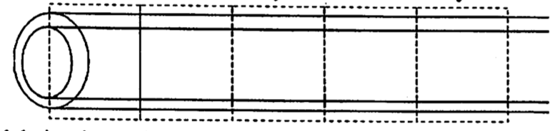
The structure of the axon is shown schematically in the figure below. For electrical purposes, an axon is basically a long, thin cylinder of membrane filled with a fluid called axoplasm. When no action potential is traveling, the potential difference across the membrane, from the outside of the axon to the inside, is about -70 mV, the restingpotential difference. In part, this is because the concentration of sodium ions (Na+) is much higher outside the axon than inside.
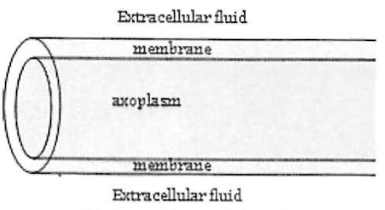
The axoplasm, like all fluids in biological systems, has mobile ions dissolved in it, giving it moderate conductivity (many orders of magnitude lower than copper or other metals we can think of as ideal conductors). The fluid outside the membrane, the extracellular fluid, is very similar to the axoplasm and thus has approximately the same conductivity.
The lipid bilayer forming the membrane is electrically insulating, with extremely low conductivity, but many different kinds of channel proteins cross the membrane. These channels only allow specific ions to pass under particular conditions. The channels increase the conductivity of the membrane as a whole, so that although the membrane conductivity is much lower than that of the axoplasm, current does pass through the membrane.
Modeling Passive Transport
Part 1: Circuit diagram
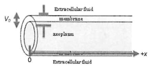
Our goal is to understand how a potential difference applied across the membrane at one end of the axon spreads along the axon if it is not being regenerated as it travels down the axon. Thus for the purposes of our model we’ll assume there is a battery at the left end of the axon segment (see the figure), holding the potential difference from the outside to the inside at x = 0 to a positive value we’ll call V0.
- Suppose there was just a single ion channel (e.g., a “potassium leak channel”) crossing through the membrane, at the right end of the segment in the figure. Current would flow through the extracellular fluid, through the ion channel, and then back through the axoplasm. The axoplasm has a resistance Raxon; the ion channel has a resistance Rmem; the extracellular fluid is assumed to be a good conductor (zero resistance).
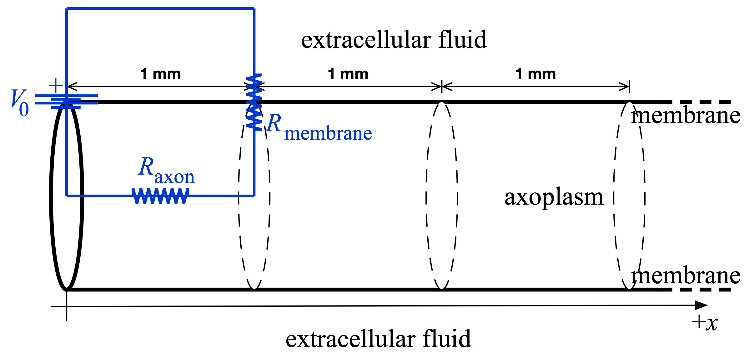 The circuit diagram corresponding to this situation is pictured above (in blue), superimposed on a sketch of the axon geometry (in black).
 - Suppose there was a second ion channel crossing the membrane, at the end of a second segment. Some additional current would flow down the axoplasm (from the first segment onward) and then through the second ion channel. Draw a circuit diagram showing this situation.
- Keep adding 1 mm-long segments until you have modeled a five-segment neuron: draw its circuit diagram.
This circuit is solvable in theory, I guess, but instead of slogging through the algebra we will build the circuit on a breadboard and just measure it.
STOP HERE. Check your circuit diagrams with the TA before proceeding.
Part 2: Resistance values
To complete the model, we need values for the resistances in the model. We will calculate the overall resistance of a membrane segment and of an axoplasm segment. The average resistivity of the membrane can be measured and used to find the resistance of a 1-mm-long segment of membrane. (In the previous section we talked about the membrane as if it contained only a single ion channel, but in reality it contains many channels (including several types); we will be lumping the electrical characteristics of all of these many channels into a single value for the resistance of the membrane segment).
Use the relationship between resistance, resistivity, length, and cross-sectional area (R = ρL/A) to estimate values for Raxon and Rmem, using the following order-of-magnitude values:
- the diameter of the axon is 10 µm
- the membrane thickness is 10 nm
- the resistivity of the axoplasm is 1 Ω·m
- the average resistivity of the membrane is 100 MΩ·m
- the segment length is 1 mm
Hint: To determine the cross-sectional area of a membrane segment, think of “unrolling” the membrane from the axon. Also, it turns out that only the ratio Raxon / Rmem affects how far the potential difference will spread.
STOP HERE. Check your resistance values with the TA before proceeding.
Add the resistance value to your circuit diagram from part 1, and take a picture for your writeup.
Part 3: Physical model
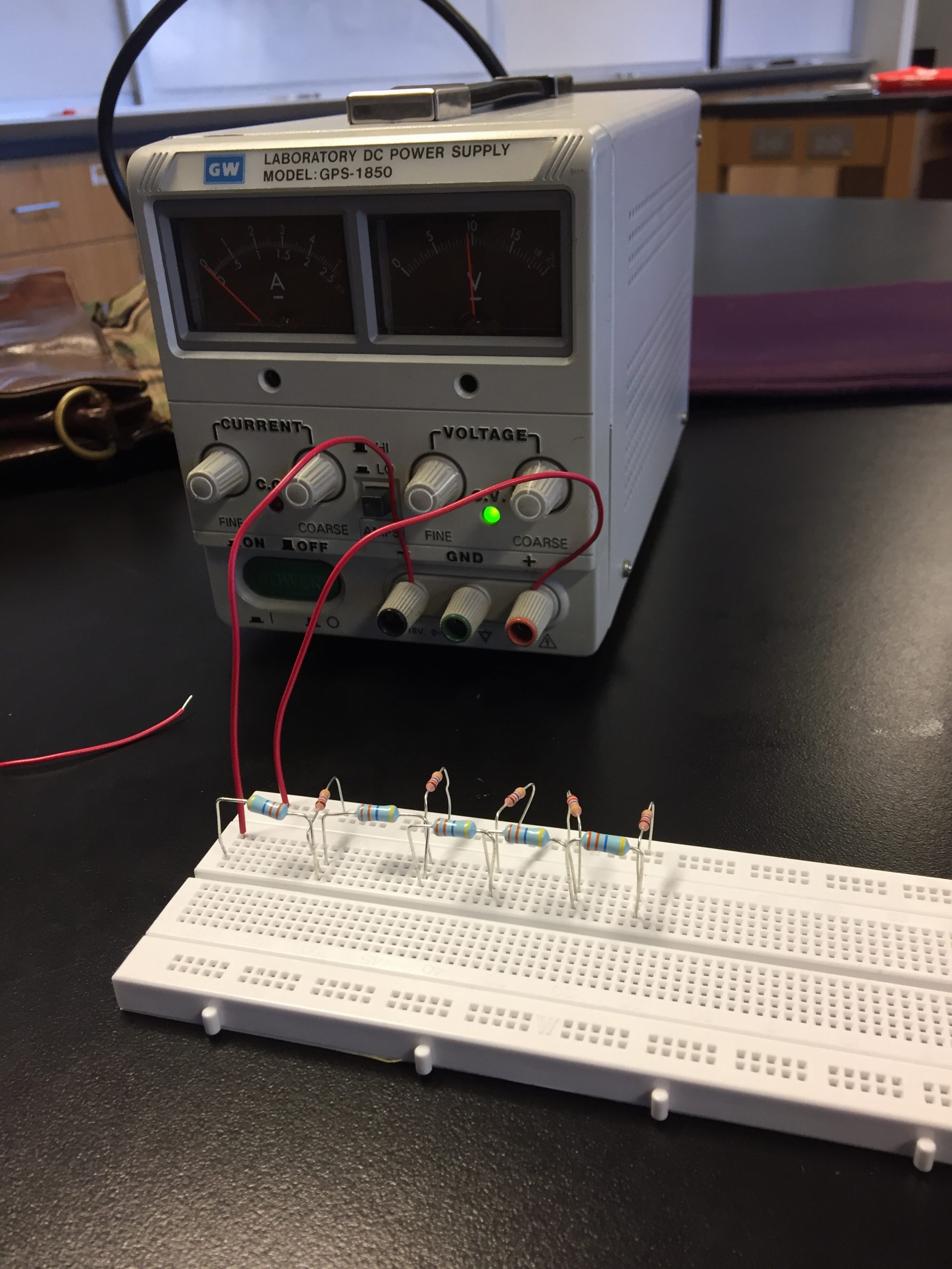 Construct your model circuit with six segments using the provided components, using resistors with the resistance values that you found in the previous part. You will need
- A 20-volt power supply
- A breadboard
- A few pieces of wire
- An assortment of resistors
- A hand-held voltmeter
Measure and record Vmem(x) for 5 segments of neuron. In your circuit, each axon resistor corresponds to a 1 mm length of neuron, so the voltages you measure on the breadboard will correspond to real neuron voltages measured at 0, 1, 2, 3, 4 and 5 mm from the cell body.
Snap a pic of your circuit to include in the writeup.
Part 4: Analysis
Plot Vmem(x) in Excel (or something similar) and fit to an exponential to determine the rate at which a passive action potential would die off along an axon.
It can be proved that the membrane voltage should decay like $$ V_{\rm mem}(x) = V_0 e^{-x/\lambda},$$ where x is the distance along the axon, and λ is the length constant (also known as the decay length) of the axon. (The derivation of this formula involves differential equations and is beyond the scope of this class. Talk to the TA if you want to see it).
For the sake of argument, let’s assume that an action potential that decays below 1% of its original size is effectively gone. What would be the maximum functional length of a neuron if it had the electrical characteristics you used in this lab, and was restricted to only passive signal propagation (as in our model)? Your answer should be much shorter than real neurons: this is why real neurons must have active (voltage-gated) ion conduction channels.
Start from this blank template of a Word document for your writeup.
Hints:
- Power Supply:
- Connect to the + and – terminal on the power supply.
- Crank the voltage knob up to maximum (about 20 V).
- Set the power supply to “lo” amp mode.
- Turn off the power when not in use. It’s probably a good idea to turn it off while you’re sticking your fingers in among the resistors.
- Breadboard:
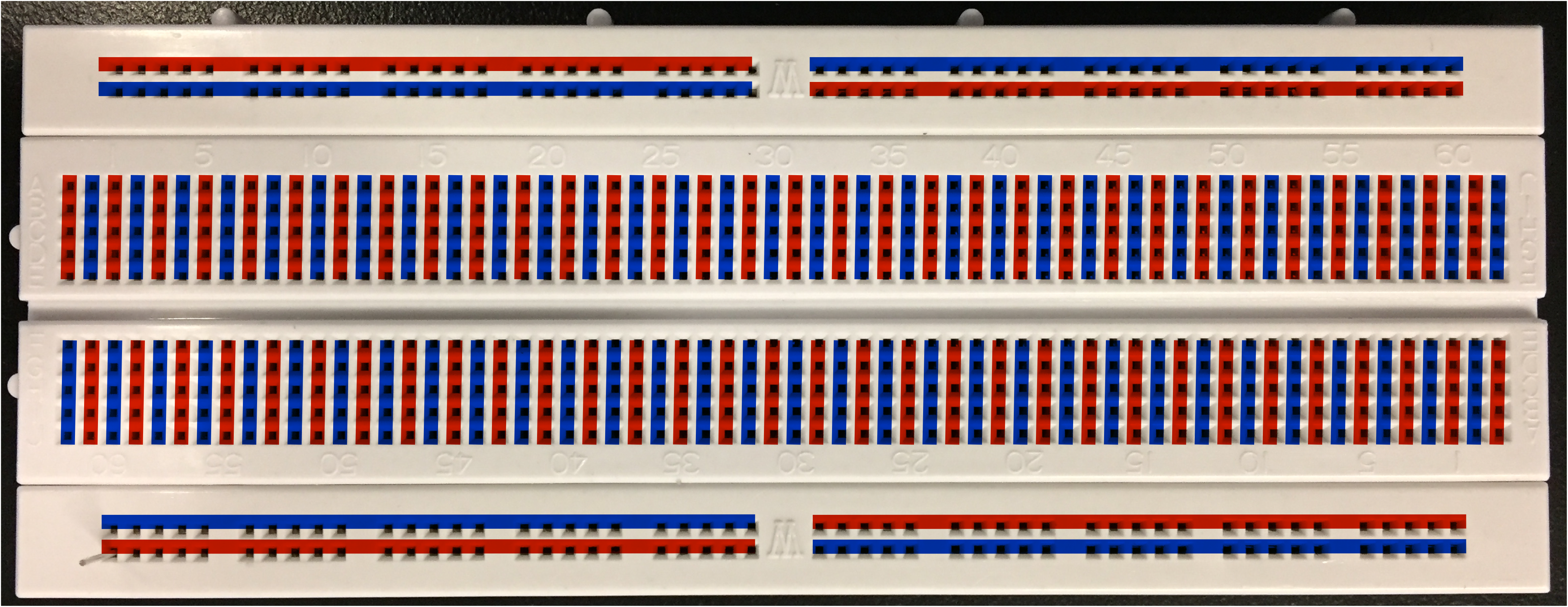
- Pay attention to which lines are connected on the breadboard. Remember that there is a connectivity gap on the top and bottom rails.
- The breadboard contains connections (not visible, under the surface) according to the pattern below
- Voltmeter:
- On the voltmeter, connect the black lead to the black “common” terminal and the red lead to the red “ohm/volt” terminal.
- Turn the meter dial to select the appropriate range of the DC voltage (20V or 2V, depending on where you’re measuring).
- You can use the ohmmeter setting to measure the resistance of a resistor if you lose track of which is which, but you will need to completely remove the resistor from the circuit to do so. You can’t use the ohmmeter setting with the resistor embedded in a circuit, particularly if there is power applied to the circuit. Alternatively, learn to read resistor color codes here.
Writeup
- Include your circuit diagram of the five-segment neuron, with resistance values written in.
- Plot Vmem(x), fit to an exponential and report the value of the decay length λ.
- What is the maximum length of a passive neuron, according to the 1% criterion outlined above? This should explain why action potentials do not propagate passively.