Motivation
Optics — the sub-field of physics focusing on the study of light — is important to many areas of biology, including vision, ecology, botany, neurobiology and molecular biology. The use of optics in biology has evolved from the simple light microscope used by Darwin to the complex, live-cell, high resolution microscopes used in current cutting-edge research. In this two-week lab, we will be exploring the behavior of light and lenses. Microscopes usually employ at least two lenses together — but, as we are only beginning to learn about light, we will be exploring single-lens systems.
You will have three main tasks in this lab:
- Measure the focal length (f) of converging (bi-convex) lenses
- Measure how the focal length (f) of a lens interacts with the image distance (i) and object distance (o), when the total distance from object to image is a fixed length (L).
- Model the i-o-f-L relationship mathematically and check that it matches your measurements.
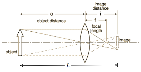
The object is the real, physical thing whose light passes through the lens; the image is the locus of light from the object arriving at a particular location. If you place a screen at the location of the image, a bright facsimile of the object will be produced (through generally of a different size, and often inverted with respect to the original). The location of the image (i) and object (o) are defined as their distances from the center of a lens; the focal length of the lens (f) is defined as the spot where parallel rays of light (rays from infinity) converge.
The distinction between object and image is not as rigid as might appear from first reading: in compound lens systems (systems with more than one lens) the image of the first lens becomes the source (the object) for the second lens.
The thin lens equation relates i, o and f:
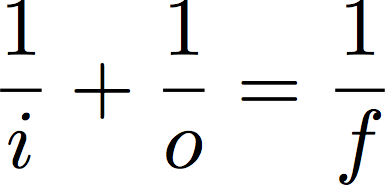 We will not prove the thin lens equation here (you will see it in lecture) but you will verify that it describes the simple lenses used in this lab.
For most microscopes, the object location and image location cannot be changed (they are a fixed distance L apart), so it is the type of lens (i.e., its focal length f) and/or the location of the lens (the image and object distances i and o) that are changed to achieve different magnifications and to focus the image. Your eye functions slightly differently: i and f are fixed but f is varied as muscles in your eyeball distort the lens of your eye:
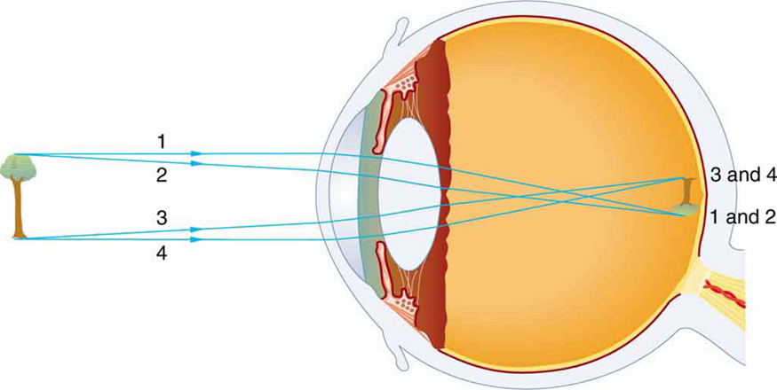
(The image on your retina is indeed upside down. Your brain has learned to flip it right-side up so you can understand it. It is possible to “unlearn” this process by wearing inversion goggles for a couple of days.)
In this lab you will ultimately determine the location of a lens that successfully produces an image on a screen a distance L away and develop a mathematical formula predicting this location.
Materials and Methods
You will assemble the light source, lenses and screen on an optical rail. This keeps them correctly aligned at the proper height but allows you to easily slide the lens back and forth to focus the image. 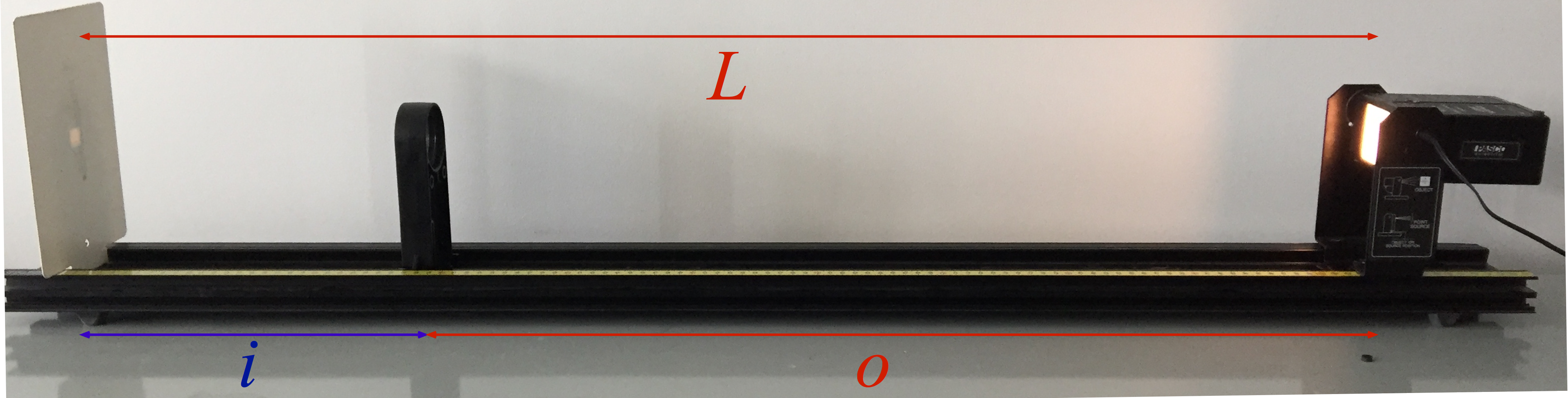
A. Determining the focal length of a lens
- Turn the light source (the object) so that it produces several bars (slits) of light directed toward the screen (the image). These slits are (almost) parallel to each other; you can verify this by looking at the slits on a piece of paper placed in the beam path: the slits look the same at any distance from the light source.
- Place the screen 50 cm from the light source.
- Clip a lens in place in between the object and image. Slide it back and forth until all the bars from the source are focused together on the screen. By definition, parallel rays of light converge at the focal point of a lens. Measure f for each lens.
- Hints / cautions:
- You can flip the light source by removing the power plug (pull on it), spreading the metal tabs that hold the light box, removing the light box and flipping it over, and reinserting it between the tabs.
- Parallel incoming rays are mathematically equivalent to an object at infinity (o = ∞). According to the thin lens equation, when o = ∞, i = f. (Check this for yourself using the equation if you’re not convinced.)
- For the light source that I used, the bars produced were not quite parallel. They acted as if o were large but not infinite. Bonus point for figuring out the effective value of o for your light source!
- You may be able to see the image more clearly if you tape a piece of white paper on the screen.
B. Construct a simple one-lens microscope
- Turn the light source (the object) so that the cross-hairs are directed towards the screen. Unlike the slits, light from the cross-hair is not emitted as parallel rays; you can verify this by trying to see the cross-hairs on a piece of paper placed in the beam path: unless the paper is right next to the light source you will see only a fuzzy bright patch.
- Measure the physical size of the object using a ruler.
- Place the screen (the image) 105 cm from the light source. Record the positions of the source and screen.
- Clip a lens in place in between the object and image.
- Slide the lens back and forth until a crisp, well-focused image is produced on the screen. Record the position of the lens and the physical size of the image.
- Find a second location where the same lens produces a well-focused image. Record the position of the lens and the physical size of the image.
- Repeat with each of the other two lenses: find two positions for each lens where a well-focused image is produced on the screen.
- Clip a lens in place in between the object and image.
- Change the source-to-screen distance to 90 cm and repeat with all three lenses.
- With one of the lenses in place and producing a well-focused, clear image, block half the object by holding a piece of paper right in front of the light source (halfway across it). What happens to the image? Block half the lens by holding a piece of paper right in front of the lens (halfway across it). What happens to the image?
- Hints / cautions:
- The cross-hairs (the object) are not flush with their mounting bracket! By my measurement they are about 2 cm back from the bracket edge. Do not neglect this extra 2 cm when setting up your distances.
- It may be hard to measure the size of small images. Do the best you can but keep in mind that this number is probably pretty inaccurate.
- You will find something strange occurs with one of the lenses when L = 90 cm. This will make sense when you work through the math later.
- You may be able to see the image more clearly if you tape a piece of white paper on the screen. You can mark the image size on the paper (and measure it at your leisure afterwards) if you like.
- To summarize: you will end up with 12 scenarios: (2 L‘s) x (3 lenses) x (2 locations). For each scenario you will record the position of the source, lens, and screen, and the size of the image.
C: Analysis
- From your position data, calculate the distance between lens and object (o) and the distance between lens and image (i).
- From your object and image size data, calculate the magnification M = [image size]/[object size], for each lens position.
- Use (A) the thin lens equation (above) and (B) the fact that the total distance between object and image is fixed at L (first at L = 105 cm; then at L = 90 cm) to construct a mathematical expressions for f(x, L). This is the required focal length f of lens, placed a distance x from an object, that successfully focuses onto a screen a distance L from the object.
- The magnification M defined as the factor by which the image size is increased compared to the original (object) size. Note that most frequently M > 1 (because that’s the whole point of constructing a microscope) but it is perfectly possible to build lens systems with M < 1: you saw this happen in several times in this lab. It turns out that the magnification is equal to the ratio of image to object distances: M = i/o. Construct an expression for M(x, L).
- Compare your measured data (from part B) to your theory (which you just wrote down):
- Plot the function f vs x twice for your two values of L; that is, plot f(x, 90 cm) and f(x, 105 cm). Add your dozen data points from the data table in part B. Do your data points line up with the function?
You can do in a couple of ways:- In Excel, make a column of a hundred or so dummy x‘s and calculate f for each x twice: once with L = 90 cm and once with L = 105 cm. Add the data points as a separate line. Your range on the x’s should be 0 < x < L, or
- Use a real function plotting program (I like desmos.com) to plot f(x, 90 cm) and f(x, 90 cm) and then add the data points to your plot. This avoids the slightly cumbersome task of making a column of dummy x’s just for plotting purposes.
- Plot the function M vs x for two values of L. Add your dozen data points from the data table in part B. Do your data points line up with the function?
- Plot the function f vs x twice for your two values of L; that is, plot f(x, 90 cm) and f(x, 105 cm). Add your dozen data points from the data table in part B. Do your data points line up with the function?
- Hints:
- Use the manufacturer’s values for the focal length of the lenses. Sorry to say it, but they’re probably more accurate that your measurements from part A.
- The object distance 0 should not appear in your formula for i(f, L). Similarly, the image distance i should not appear in your formula for o(f, L).
- See the online reading for a geometrical proof that M = –i/o; the additional negative sign simply indicates that the image is inverted (flipped) relative to the object. Since we aren’t keeping track of the orientation of the image we just drop the negative sign.
Writeup
Use the Lab 09 blank template for your writeup.
Questions to be answered
- Part A: For each of three lenses, you have the measured focal length as well as the nominal focal length (molded onto the lens). How well do they agree?
- If the measured focal length is consistently longer than the nominal one, this probably means that your multiple-line light source was not accurately acting like a source at infinite distance (that is, the multiple lines were not emerging from the source in parallel) . If so, explain and/or calculate the effective object distance of your light source.
- Part B: For each of the three lenses (three value of f), for each of the two image-object distances (two values of L), you have measured two lens positions x that produce a well-formed image.
- How well do your measured f’s agree with the theoretically predicted f‘s?
- How well do your measured M‘s agree with the theoretically predicted M‘s?
- There are lenses (some values of f) that – for a particular L – can never produce a focused image. Figure out (and justify your answer) the largest f that can (for some value of x) make a good image. That is, look at your function f(x, L) and figure out fmax(L)
- Why does the image react differently when half the object is blocked, compared to when half the lens is blocked?
- Hints:
- Think about tracing the rays from object to image; which rays are blocked by the paper?
- This website or this applet may help you develop some intuition about how light propagates from an object, through a lens, to the image.
- When your pupil (located near the lens of your eye) contracts in bright light it doesn’t cut off your field of view: this is the same phenomenon we are investigating here.
- Hints:
Hints
- Be sure to measure the object distance from the face of the source, not the edge of the bracket that holds the source.
- Be consistent: measure everything in m (or in cm or mm – just don’t mix them)
- The light source should be centered and at the same height as the lenses. You may need to flip the light around if it’s misaligned.
- Use a ruler to measure the image sizes. You may need to estimate for small sizes; that’s OK.
- Only record a value if the image is really in focus! Some lens / distance combinations were deliberately chosen to not successfully produce a good image.